
Logic Gates: The fundamental functional units of a digital circuit are logic gates. These gates form the foundation for all the digital devices working in the universe. In the absence of these gates, the digital world will come to a halt. So, we can now understand the inevitability of this concept. To acquaint students with the functionality and logic behind these gates, they are introduced to the world of these gates in the Class 12 Physics NCERT book. This chapter plays an important role in building a solid background for understanding different concepts of semiconductors and diodes. For this sake, we have provided students with detailed notes PDFs and video explanations of this topic that will help them score good marks in this concept in the board as well as NEET exam.
Logic Gates
Understanding logic gates is crucial if you’re studying electronics. These are significant electronic gadgets, mostly based on the Boolean function. These gates are used to provide a single binary output after performing logical operations on one or more binary inputs. Essentially, the electronic circuits within a digital system are known as logic gates. These gates are found in the majority of modern electronic equipment. As an illustration, these magic gates can be found in memory devices, smartphones, and tablets. Understanding the nature and functioning of different types of these gates will prepare students for the competitive exam like NEET. To facilitate the process of learning, we have provided students with the detailed notes on this concept along with their PDF and expert video explanation.

Logic Gates Definition
As per the formal definition, logic gates are basic switching circuits used in digital circuits to decide whether an input pulse can pass through to the output. These gates carry out a variety of logical operations necessary for any digital circuit and are the fundamental components of a digital circuit. These have a single output but can accept two or more inputs. A logic gate’s output is determined by the combination of inputs applied across it. Boolean algebra is used by logic gates to carry out logical operations.
Boolean algebra is kind of a logical algebra where symbols stand in for logic levels. The logic levels in this algebra are represented by the digits (or symbols) 1 and 0. In electrical circuits, logic 1 will stand for a closed switch, a high voltage, or a device in the “on” state. Logic 0 will indicate an open switch, low voltage, or “off” state for the device. Almost every digital device we regularly use contains logic gates. Our phones, computers, tablets, and memory devices are all built with these magical gates.
Types of Logic Gates
There are only three types of basic logic gates. All other gates are made by using the combination of these three gates. The three types of basic logic gates are given below.
1) AND Gate
A single output and two or more inputs make up an AND gate. This gate produces a 1 output when every input is 1. When there are two inputs, A and B, the AND gate’s Boolean logic is Y=A.B.
2) OR Gate
An OR gate can have one output and two or more inputs. This gate’s logic states that its output will be 1 if at least one of its inputs is 1. If there are two inputs, A and B, the OR gate’s output will be determined by the following mathematical process: A+B=Y
3) NOT Gate
A simple one-input, one-output gate is the NOT gate. The output is zero when the input is one, and vice versa. Because of this function, a NOT gate is also sometimes referred to as an inverter. The Boolean equation Y=A’ can be used to calculate the output if there is just one input, A.
Apart from these gates, other types of logic gates are:
I) NAND Gates
A NAND gate is essentially an AND gate that comes after a Not gate. It is also referred to as a “NOT-AND” gate. The output of this gate is only zero if none of the inputs are zero. On the other hand, the output is high when there is at least one low input and all of the inputs are not high. The Boolean expression for the NAND gate, given two inputs A and B, is Y=(A.B)’.
II) NOR Gates
An OR gate and a NOT gate come together to form a NOR gate, also referred to as a “NOT-OR” gate. The output of this gate is only 1 when none of its inputs are 0. On the other hand, when every input is low, the result is high. If there are two inputs, A and B, the Boolean statement for the NOR gate is Y=(A+B)’.
III) XOR Gates
A digital logic gate known as an Exclusive-OR, or “Ex-OR,” gate takes more than two inputs but only outputs one value. The XOR Gate’s output is “High” if any of the inputs are “High.” When there are two “high” inputs, there is a “low” output. The output is “Low” if both inputs are “Low.” Y=A’ is the Boolean equation pertaining to the XOR gate. If there are two inputs, A and B, then B+A.B’.
IV) XNOR Gates
A digital logic gate known as an Exclusive-NOR, or “EX-NOR,” gate can receive more than two inputs but can only output one. The XNOR Gate’s output is “High” if both inputs are “High.” When both inputs are “Low,” “High” is the result. The output is “Low” if one of the inputs is “Low.” The Boolean equation for an XNOR gate with two inputs, A and B, is Y=A.B+A’B’.

Universal Logic Gates
There are two types of these digital gates that are known as universal logic gates. These are NAND Gates and NOR Gates. These are known as Universal gates because all other types of logic gates can be expressed in the form of these gates. In other words, we can make any gates by replacing them with NAND or NOR gates. Any Boolean function can be implemented by a universal gate without the requirement for any other form of gate. In actuality, this is helpful because NAND and NOR gates—which are the fundamental gates utilized in all IC digital logic families-are less expensive and simpler to produce. The symbols and truth table of all the types of gates are mentioned in the subsequent sections.
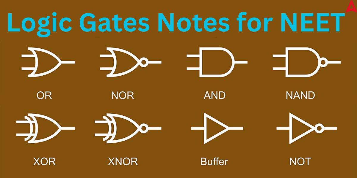
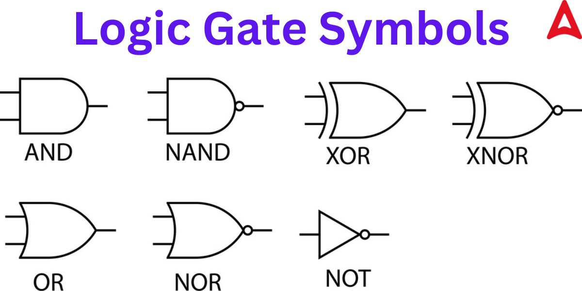
Logic Gate Symbols
The different types of gates are represented using different symbols for the sake of simplicity. As in most cases, these gates must be shown in the circuit building, so, knowing the symbols of different types of gates becomes highly important. The symbols of different gates are shown below.
Logic Gates Truth Table
A truth table is the term used to describe the table that is used to represent the Boolean statement of a logic gate function. A truth table for a logic gate displays every possible combination of inputs for the gate or circuit along with the output that will be produced based on the combination of these input(s). The truth table for different types of gates is given below.
1) AND Gates
| Input 1 | Input 2 | Output |
| 0 | 0 | 0 |
| 0 | 1 | 0 |
| 1 | 0 | 0 |
| 1 | 1 | 1 |
2) OR Gates
| Input 1 | Input 2 | Output |
| 0 | 0 | 0 |
| 0 | 1 | 1 |
| 1 | 0 | 1 |
| 1 | 1 | 1 |
3) NOT Gates
| Input | Output |
| 0 | 1 |
| 1 | 0 |
4) NAND Gates
| Input 1 | Input 2 | Output |
| 0 | 0 | 1 |
| 0 | 1 | 1 |
| 1 | 0 | 1 |
| 1 | 1 | 0 |
From the truth table observation of the NAND gate, we can see that the output of this gate is polar opposite to that of the AND gate as expected.
5) NOR Gates
| Input 1 | Input 2 | Output |
| 0 | 0 | 1 |
| 0 | 1 | 0 |
| 1 | 0 | 0 |
| 1 | 1 | 0 |
From the truth table observation of the NOR gate, we can see that the output of this gate is polar opposite to that of the OR gate as expected.
6) XOR Gates
| Input 1 | Input 2 | Output |
| 0 | 0 | 0 |
| 0 | 1 | 1 |
| 1 | 0 | 1 |
| 1 | 1 | 0 |
7) XNOR Gates
| Input 1 | Input 2 | Output |
| 0 | 0 | 1 |
| 0 | 1 | 0 |
| 1 | 0 | 0 |
| 1 | 1 | 1 |
Logic Gates PDF
The detailed notes of this concept have been created by the expert Physics faculty of Adda 247 for board and competitive exam. The PDF not only contains detailed explanation of different concepts but also have many important PYQs with solutions to help students in their preparation.
Download Logic Gates Class 12 Notes PDF
Logic Gates Video
Knowing the importance of this concept for the the board and competitive exam, a dedicated video has been made by the expert Physics faculty to help students in their journey of cracking the NEET UG exam. The video contains detailed explanation of every minute concepts. After going through the video, students will be able to tackle any problem related to this concept.


 Physics Investigatory Project Class 12 T...
 CBSE Class 12 Physics Viva Questions wit...
 Trigonometry Notes for NEET, Download PD...