
Full Wave Rectifier
A full-wave rectifier converts both halves of each cycle of an alternating wave (AC signal) into a pulsing DC signal. To convert AC voltage to DC voltage, full-wave rectifiers are utilised, which require numerous diodes to build. The technique of converting an AC signal to a DC signal is known as full wave rectification.
Full Wave Rectifier Circuit
Rectifiers are circuits that convert alternating current (AC) to direct current (DC). The rectifiers are full-wave rectifiers if they rectify both the positive and negative half cycles of an input alternating waveform. A collection of diodes is used in full-wave rectifiers to achieve this. A diode only allows current to flow in one direction and prevents it from flowing in the opposite way. This approach is used to build various rectifiers.
Efficiency of Full Wave Rectifier
The efficiency of a full-wave rectifier is a measure of how effectively it converts alternating current (AC) input voltage into direct current (DC) output voltage while minimizing power losses. Full-wave rectifiers are often used to convert AC voltage into a smoother DC voltage for various electronic applications.
The efficiency () of a full-wave rectifier can be calculated using the following formula:
Where:
- is the efficiency expressed as a percentage.
- is the DC power output (the average power of the rectified DC voltage).
- is the AC power input (the average power of the AC voltage source).
In a full-wave rectifier, the DC power output () can be calculated as follows:
Where:
- is the DC voltage across the load resistor.
- is the DC current through the load resistor.
The AC power input () can be calculated as follows:
Where:
- is the root-mean-square (rms) value of the AC voltage input.
- is the rms value of the AC current input.
To find the efficiency of a full-wave rectifier, you’ll need to measure or calculate the relevant voltage and current values. It’s important to note that real-world rectifiers may have some inherent losses due to factors like diode forward voltage drops and resistance in the components, which can reduce the overall efficiency.
Efficiency is an essential parameter to consider in power supply and conversion applications because it indicates how effectively the rectifier is converting AC power into DC power without unnecessary losses. Higher efficiency is generally desirable as it results in less wasted energy and reduced heating of the components.
Full Wave Rectifier Types
There are two categories in which Rectifiers can be divided: Half Wave Rectifiers and Full Wave Rectifiers
Half Wave Rectifier
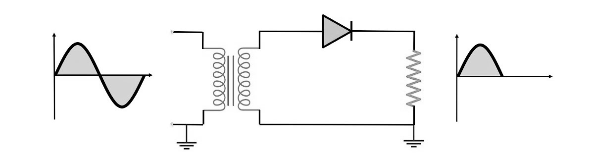
When we utilise a half-wave rectifier, we waste a lot of power since only half of each cycle passes through while the other cycle is blocked. Furthermore, the half-wave rectifier is inefficient (40.6 percent), so it can’t be used for applications that require a smooth and consistent DC output. A full wave rectifier is used to produce a more efficient and stable DC output.
Full Wave Rectifier
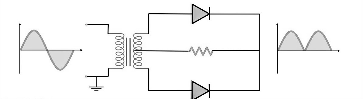
Two diodes are now utilised in a Full Wave Rectifier circuit, one for each half of the cycle. The secondary winding of a multiple winding transformer is split evenly into two halves with a common centre tapped connection (C).
When the anode terminal of each diode is positive with respect to the transformer centre point C, each diode conducts in turn, producing an output throughout both half-cycles, double that of the half-wave rectifier, making it 100 percent efficient.
Full Wave Rectifier Formula
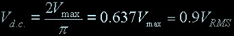
Because the intervals between each half-wave created by each diode are now filled in by the second diode, the average DC output voltage across the load resistor is now double that of the single half-wave rectifier circuit and is approximately 0.637Vmax of the peak voltage, assuming no losses.
VRMS = 0.7071VMAX, where VMAX is the maximum peak value in one half of the secondary winding and VRMS is the rms value. IDC = VDC/R is the formula for DC current.
If each half of the transformer windings has the same rms voltage value, the output waveform’s peak voltage is the same as before for the half-wave rectifier. Different transformer ratios can be utilised to get different DC voltage outputs.
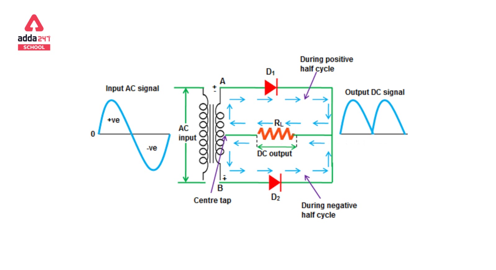
Full wave Rectifier Diagram
The full wave rectifier diagram is given below.
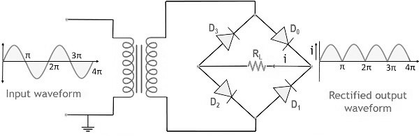
Full wave Rectifier Working
The full wave rectifier’s input AC is extremely high. The rectifier circuit’s step-down transformer converts high-voltage AC to low-voltage AC. The load resistor is connected to the anode of the centre-tapped diodes, which is connected to the secondary winding of the transformer. The top half of the secondary winding becomes positive during the positive half cycle of the alternating current, while the second half of the secondary winding turns negative. Diode D1 is forward-biased during the positive half cycle because it is connected to the secondary winding’s top, whereas diode D2 is reverse-biased since it is connected to the secondary winding’s bottom. As a result, diode D1 will conduct as a short circuit, but diode D2 will not conduct as an open circuit.
Because the top half of the secondary circuit becomes negative and the bottom half of the circuit becomes positive during the negative half cycle, diode D1 is reverse-biased and diode D2 is forward-biased. DC voltage is obtained for both the positive and negative half cycles in a full wave rectifier.
The Positive Half-cycle
The Negative Half-cycle
As the current flowing through the load is unidirectional, so the voltage developed across the load is also unidirectional the same as for the previous two diode full-wave rectifier, therefore the average DC voltage across the load is 0.637Vmax.
Full wave Rectifier Advantages and Disadvantages
Advantages
The key benefit of this bridge circuit is that it does not require a specific centre tapped transformer, which reduces the size and expense of the circuit. The load is connected to one side of the diode bridge network, while the single secondary winding is connected to the other. The other advantages of a full wave rectifier are:
- The frequency of the ripple of a full wave rectifier is two times that of the input.
- The efficiency of a full wave rectifier is much more than half wave rectifier.
- The full wave rectifier has the high DC power output.
- The ripple factor in a full wave rectifier is reduced.
- Because the ripple voltage in a full wave rectifier is low and the frequency is higher, only a basic filtering circuit is needed.
- The full wave rectifier has more output voltage.
- The factor of transformer use is higher in full wave rectifier.
- Both parts of the AC waveform are used in a full wave rectifier.
- Using the ripple frequency of a full wave rectifier makes it easier to offer smoothing.
Disadvantages
The disadvantages of a full wave rectifier are as follows:
- Comapred to a Half-wave rectifier, a full-wave rectifier is much more complex.
- For a full wave rectifier, two diodes for the centre tap rectifier and four for the bridge rectifier are required.
- The diode’s PIV rating for a full wave rectifier is greater.
- PIV diodes with a higher PIV of a full wave rectifier are larger and more expensive.
- The centre tap transformer of a full wave rectifier is expensive.
- On an audio circuit in a full wave rectifier, the double frequency hum may be more perceptible.
- The middle tap on the secondary winding of a full wave rectifier is difficult to locate.
- Because each diode only uses one-half of the transformer secondary voltages in a full wave rectifier, the DC output is modest.
- The full-wave rectifier circuit is ineffective when only a little voltage needs to be rectified.
Average DC voltage across the load in terms of vmax is
The average DC voltage across a load, Vavg, in a circuit that has a maximum voltage (Vmax) can be calculated using the formula:
Where:
- is the average DC voltage across the load.
- is the maximum voltage (peak voltage) across the load.
- (pi) is approximately equal to 3.14159.
This formula assumes that the voltage waveform is a pure sinusoidal AC voltage. If the waveform is different from a sine wave or if it’s a more complex waveform, then the calculation for average voltage may be different.
Read More About:
- Dielectric Constant- Definition, Formula, Meaning In Chemistry
- Limestone- Chemical Formula, Uses, Meaning
- Cannizzaro Reaction – Definition, Examples, Mechanism
- Lifecycle Of Silkworm- Diagram, Drawing, Project
- Scattering Of Light- Examples, Definition, Discovery, Prism


 Best NEET UG Counselling Course 2026: Wh...
 Haryana NEET Counselling 2026: Registrat...
 Gujarat NEET Counselling 2026: Registrat...