
Bridge Rectifier: A bridge rectifier converts an alternating current (AC) signal to a direct current (DC) using a diode bridge. Rectifiers are primarily employed in power supplies, supplying DC voltage to electronic equipment. Half-wave rectifiers, full-wave rectifiers, and bridge rectifiers are the three most prevalent types of rectifiers. All of these rectifiers convert alternating current (AC) to direct current (DC). A diode bridge rectifier is a bridge circuit arrangement of four or more diodes in which two circuit branches are connected by a third. Full-wave rectification is provided by a bridge rectifier.
Bridge Rectifier
What is a Bridge Rectifier? A rectifier (including a Bridge Rectifier) is an electrical circuit that turns an AC current voltage input into a direct current voltage at the output end. Because a diode can only conduct current in one direction, the current has to follow different courses through the diode bridge rectifier based on the polarity of the input. In each situation, the output polarity stays constant.
When an AC current is applied, the current follows one path during the positive half-cycle and the other during the negative half-cycle. Because the signal still varies in magnitude but no longer in direction, this results in a pulsing DC output. Simultaneously, the bridge rectifier circuit with four diodes also enables low-cost full-wave rectification by utilizing two diodes during each half cycle.
Construction of Bridge Rectifier Circuit
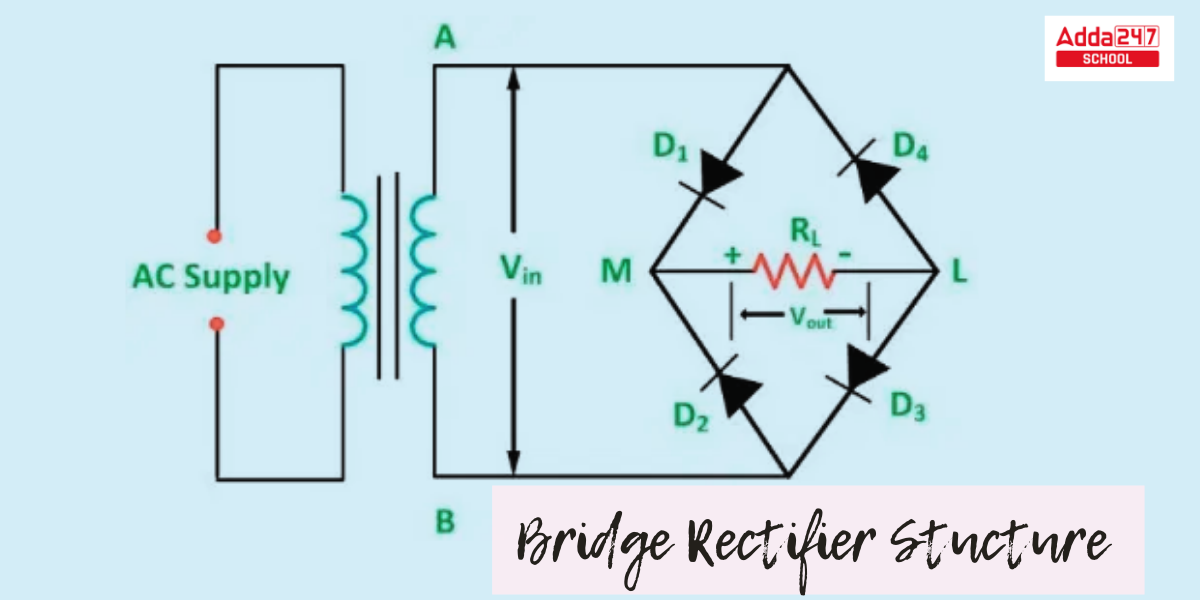
A single-phase bridge rectifier is built by connecting four diodes (D1, D2, D3, and D4) in an enclosed loop configuration to produce a bridge. The diodes are wired together in such a way that they participate in pairs during positive half cycles. The primary benefit of bridge rectifier arrangement is that it saves space and money by eliminating the need for an expensive center-tapped transformer. The construction of the Bridge Rectifier is described below in a simpler way.
- These four diodes – D1, D2, D3, and D4 – are linked in a closed-loop design that converts alternating current to direct current effectively.
- The input AC signal is applied to Terminals A and B, and the output DC signal is obtained through Resistor RL, which is linked between M and L terminals.
- Only two diodes, D1 and D3, flow electric currents throughout the positive half cycle, whereas D2 and D4 conduct electric currents within the negative half cycle.
- This transformation will continue as long as the current flows.
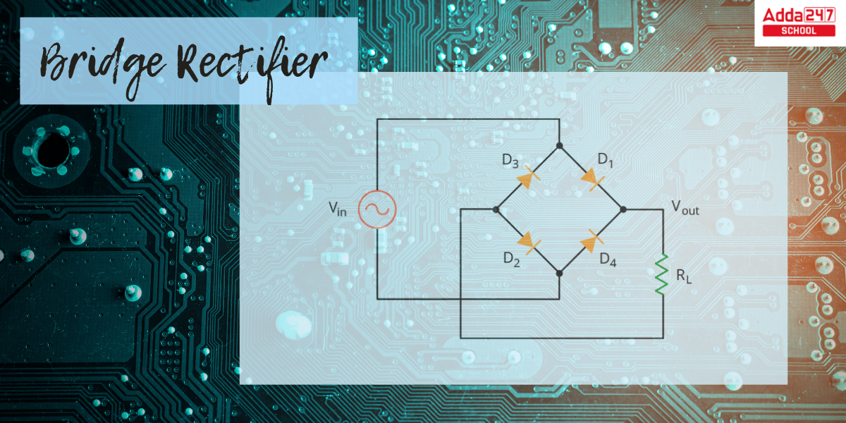
Bridge Rectifier Circuit Diagram
Bridge Rectifier Circuit Diagram is given below. check all components of bridge rectifier.
Bridge Rectifier Working Principle
When an input signal is applied across a bridge rectifier, the signal alternates between positive and negative cycles.
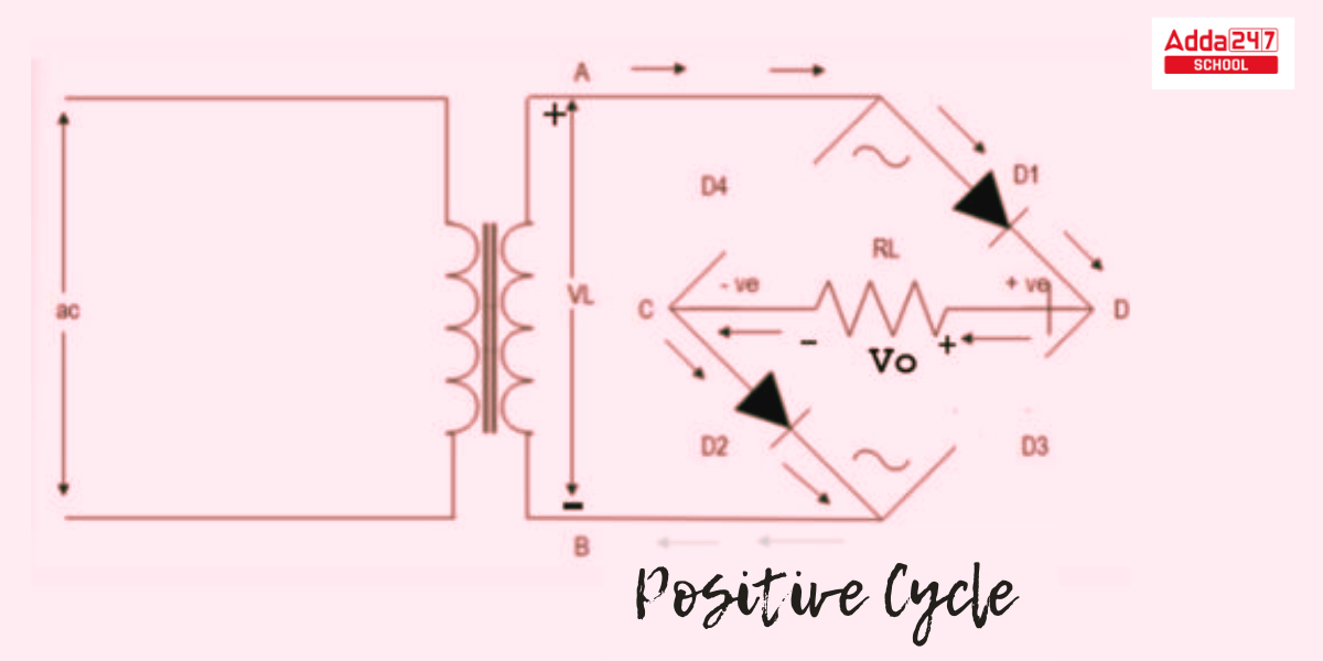
Bridge Rectifier Operation in Positive Half Cycle
- The polarity of the secondary voltage crossing terminal A is positive with with regard to terminal B throughout the positive half cycle of the input AC supply (0 to π).
- As a result, Diodes D1 and D2 are forward-biased, whereas Diodes D3 and D4 are reverse-biased.
- D1 and D2 diodes form a short circuit and begin conducting, whereas D3 and D4 diodes are open circuits.
- The load current begins to flow via the short circuit channel formed by D1 and D2.
- The load current is flowing from D1, RL, to D2. At terminal interface D, the voltage throughout load resistor RL is positive, while at terminal C, it is negative.
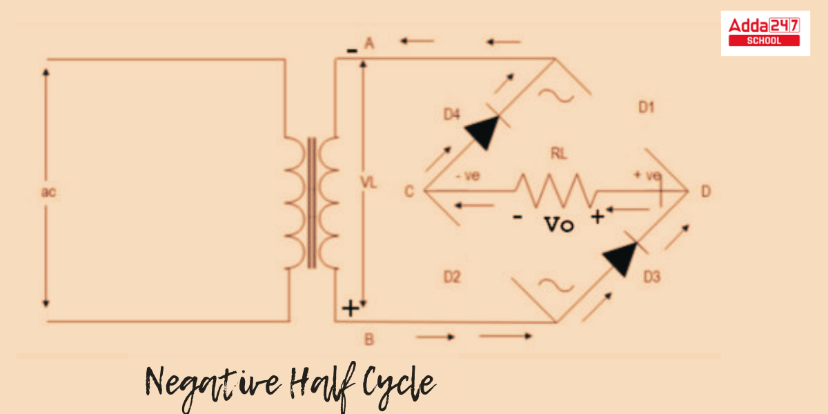
Bridge Rectifier Operation in Negative Half Cycle
- The polarity of the secondary voltage crossing terminal B is positive with comparison to terminal A during the negative half cycle of the input AC supply ((π to 2(π).
- D3 and D4 diodes form a short circuit and begin carrying out, but D1 and D2 diodes are open circuits. The load current begins to flow along the short circuit channel formed by D3, and D4 diodes.
- The load current is flowing from D3, RL, to D4. At terminal D, the voltage throughout load resistor RL is positive, while at terminal C, it is negative.
- It should be observed that Diodes D1, D2, D3, and D4 alternately conduct in half cycles. These diode pairs are not operating at the same moment.
- The load current flows during the positive half cycles of the input AC voltage and in the same channel via the load resistor RL in both cycles.
- The polarity of the voltage over RL corresponds to the direction of the load current across the conducting states of diodes D1, D2, D3, and D4. The output pulse can be totally positive or completely negative.
- The obtained output pulse is positive in this case. This unidirectional current denotes direct current. As a result, at the output, the input AC voltage is transformed to DC voltage.
- The final result The corrected pulse has a pulsing character. We must add a filter capacitor to the output to clean this up so that we may obtain a pure DC voltage.
Properties of Bridge Rectifier
A bridge rectifier has the following features:
- Efficiency
- Peak Inverse Voltage
- Ripple Factor
Efficiency of Bridge Rectifier
- The efficiency of a Bridge Rectifier is simply how effectively the bridge rectifier transforms AC to DC. The Bridge Rectifier’s efficiency can be calculated as the ratio of DC output power to AC input power.
- The Bridge Rectifier Efficiency formula is as follows:
- The Bridge Rectifier’s efficiency should be around 81.2%.
Peak Inverse Voltage of Bridge Rectifier
- Peak Inverse Voltage is the maximum voltage that a diode can sustain when reverse-biased.
- Throughout the positive half cycle, diodes D1 and D3 conduct electricity, while diodes D2 and D4 are non-conducting.
- In a comparable manner during the negative half cycle, diodes D2 and D4 are conducting, while diodes D1 and D3 are non-conducting.
Ripple Factor
- The fraction of alternating current (or ripples) in the rectified DC output is known as the ripple factor. Ripple Factor is defined as the smoothness of the output DC signal.
- A smooth DC signal is one that has fewer ripples in its output DC signal. A pulsing DC signal has more ripples than a steady-state DC signal.
- The ripple factor is the ratio of ripple voltage to pure DC voltage. Ripple Factor need to be kept to a minimum. We utilize a filter capacitor at the output to lower this factor.
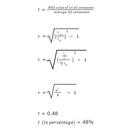
- The ripple factor is calculated as follows:
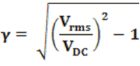
Vrms = Root Mean Square Voltage.
VDC = Average Voltage of DC Supply
- A Bridge rectifier’s ripple factor is assumed to be 0.48.
Benefits of Bridge Rectifier
The benefits of a bridge rectifier are explored more below.
- Bridge rectifiers are more efficient than half-wave rectifiers.
- A half-wave rectifier employs just half of the incoming AC signal and blocks the other half. A half-wave rectifier dissipates half of the input signal. Electric current is permitted in a bridge rectifier during both the positive and negative half cycles of the input AC signal. As a result, the output DC signal is nearly equivalent to the input AC signal.
- A bridge rectifier offers the same efficiency as a center-tapped full-wave rectifier.
- The output DC signal of a bridge rectifier is smoother than the output DC signal of a half-wave rectifier.
- In contrast to a half-wave rectifier, current may circulate during positive as well as negative cycles. As a result, the output DC signal is nearly equivalent to the input AC signal.
Bridge Rectifier’s Limitations
Bridge Rectifier offers some drawbacks to those discussed below.
- The power loss of the bridge rectifier is significant.
- Only one diode connects during each half cycle of a center-tapped full-wave rectifier. In a bridge rectifier, on the other hand, two diodes coupled in series conduct throughout each half cycle. As a result, the voltage drop in a bridge rectifier is greater.
- A bridge rectifier’s circuit is more complicated than that of a half-wave rectifier or a center-tapped full-wave rectifier.
- Bridge rectifiers require four diodes, whereas half-wave and centre-tapped full wave rectifiers need only two.


 NEET OMR Sheet 2026 Out, Download Respon...
 NEET 2026 Counselling Security Fees: How...
 Is Adda247 Worth It for CUET Preparation...